This post is a continuation of my previous post. I integrated my DES IP block into a hardware design to run on the Xilinx Zynq7000 FPGA as a software peripheral.
Disclaimer: I am a complete Verilog novice. I'm certain there are bad design/bad practice/bugs in this implementation. Eventually I intend for someone knowledgeable to review and critique my work in an effort to improve.
I started the processing system/software integration with a basic Zynq7000 IP core as I did in my "hello world" LED project. I won't go into detail because the process was essentially the same as I wrote up in that post; i.e. packaging my DES core as an AXI peripheral and creating a design alongside the Zynq7000 processing system. The following block diagram shows the design. Most of the design is an artifact of Vivado's block and connection automation features.
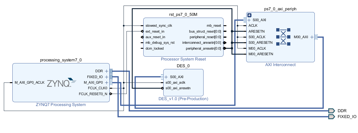
The DES_0 module is my DES IP. It's an AXI peripheral with eight 32-bit registers. Starting from Vivado's AXI peripheral boilerplte, I instantiated a DES module. I tied the clock input to the same clock as the AXI bus.
// Add user logic here
    DES des (
        .clock(S_AXI_ACLK),
        .mode(mode),
        .enable(enable),
        .key(key),
        .input_data(input_data),
        .output_data(output_data),
        .valid(valid)
    );
I added the remaining wires and registers to the top of the Vivado-generated code.
//Mode input
reg mode = 0;

//Enable input
reg enable = 1;

//Key input register
reg [63:0] key = 0;

//Input register
reg [63:0] input_data = 0;

//Ciphertext output
wire [63:0] output_data;

//Valid bit output
wire valid;
Next, I added an always block to tie several of the AXI registers to the DES module. I used AXI slave register 1 as the DES control register, DES_CTRL as referenced in the software (below). Bits 0 and 1 are enable and mode, respectively. The next two slave registers are used for the left and right halves of the 64-bit key, DES_KEYL and DES_KEYR. I use the terminology "left" and "right" as opposed to "most significant" and "least significant" because the DES algorithm description uses the former. Similarly, the next two registers are for the 64 bits of input data, DES_IDL and DES_IDR.
    always @(*)
    begin
        enable      <= slv_reg1[0];
        mode        <= slv_reg1[1];
        key         <= {slv_reg2, slv_reg3};
        input_data  <= {slv_reg4, slv_reg5};
    end
I mapped the AXI read operations to provide a version (the date in this case), DES_VER, the state of DES_CTRL with the additon of the valid output, and the left and right halves of the 64-bit output data, DES_ODL and DES_ODR.
	// Implement memory mapped register select and read logic generation
	// Slave register read enable is asserted when valid address is available
	// and the slave is ready to accept the read address.
	assign slv_reg_rden = axi_arready & S_AXI_ARVALID & ~axi_rvalid;
	always @(*)
	begin
	      // Address decoding for reading registers
	      case ( axi_araddr[ADDR_LSB+OPT_MEM_ADDR_BITS:ADDR_LSB] )
	        3'h0   : reg_data_out <= 32'h09252019;
	        3'h1   : reg_data_out <= {29'b0, valid, mode, enable};
	        3'h2   : reg_data_out <= output_data[63:32];
	        3'h3   : reg_data_out <= output_data[31:0];
I packaged this module, generated my block design, and synthesized/exported the hardware. I had a few critical warnings and some bugs I had to chase down to facilitate synthesis. Originally, in my DES module, I had updated the validity bits by OR'ing the op_valid register with a bit mask for each step, e.g.
op_valid = op_valid | KEYS_VALID;
This led to the op_valid register having "multiple drivers". I resolved this issue by setting the bits of the mask individually, e.g.
op_valid[KEYS_VALID] = 1;
After resolving the synthesis warnings, I was able to complete the implementation and export the hardware.
I created a new Vitis C++ application project using my exported hardware as the platform. First, I created a registers class to handle operations on the AXI registers. In a real project, I would spend more time here, possibly making the class a singleton and enforcing mutual exclusion for register access. For this proof-of-concept, I kept it simple. First, I defined meaningful names for the register addresses.
#define DES_BASE 0x43c00000

///Read Registers
#define DES_VER 	DES_BASE
#define DES_CTRL 	DES_BASE + 4
#define DES_ODL 	DES_BASE + 8
#define DES_ODR 	DES_BASE + 12

//Write Registers
#define DES_KEYL DES_BASE + 8
#define DES_KEYR DES_BASE + 12
#define DES_IDL  DES_BASE + 16
#define DES_IDR  DES_BASE + 20
I added helper functions for reading and writing to the registers, as well as for setting or clearing individual bits (which I didn't end up using but will be useful snippets to have in the future, I'm sure).
    uint32_t regRead(uint32_t addr)
	{
		return *(uint32_t*)addr;
	}

	void regWrite(uint32_t addr, uint32_t val)
	{
		*((uint32_t*)addr) = val;
	}

	void setBit(uint32_t * val, uint32_t bit)
	{
		*val = *val | bit;
	}

	void clearBit(uint32_t * val, uint32_t bit)
	{
		*val = *val & ~(bit);
	}
Next, I created a class for DES operations. In the constructor, I ensure that the module is disabled (similarly in the destructor).
DES::DES()
{
	//Make sure the module is disabled
	reg.regWrite(DES_CTRL, 0x0);
}
DES::~DES()
{
	//Make sure the module is disabled
	reg.regWrite(DES_CTRL, 0x0);
}
Next I added a routine to read the version register, DES_VER.
uint32_t DES::getVersion()
{
	//Read the version register
	return reg.regRead(DES_VER);
}
I added a routine to perform encryption with two arguments, the plaintext, plain, and the key, key, both 64-bit unsigned integers. The routine returns the 64-bit cipher text. First, the routine writes the key halves into the DES_KEYL and DES_KEYR registers.
uint64_t DES::encrypt(uint64_t plain, uint64_t key)
{
	//Set the key
	reg.regWrite(DES_KEYL, (key >> 32) & 0xFFFFFFFF);
	reg.regWrite(DES_KEYR, (key & 0xFFFFFFFF));
Next, the input data is written to DES_IDL and DES_IDR.
    //Set the input data
	reg.regWrite(DES_IDL, (plain >> 32) & 0xFFFFFFFF);
	reg.regWrite(DES_IDR, (plain & 0xFFFFFFFF));
The control register is then written with encryption mode, 0 in the mode bit position, and enable, 1 written in the enable position.
    //Set mode to encrypt, enable
	reg.regWrite(DES_CTRL, 0x1);
Enabling the module starts the encryption process. When the DES block is finished, the valid bit is set in the DES_CTRL register. A polling loop blocks until this bit is set.
	//Poll for validity
	uint32_t ctrl = reg.regRead(DES_CTRL);
	while(!(ctrl & 0x5))
	{
		ctrl = reg.regRead(DES_CTRL);
	}
Once the validity bit is set, the output data registers, DES_ODL and DES_ODR are read and combined into the ciphertext to be returned.
	//Read the output data
	return (uint64_t)reg.regRead(DES_ODL) << 32 | reg.regRead(DES_ODR);
The decryption routine is nearly identical, the only difference being the DES_CTRL register which is written with the mode bit set to decryption.
	//Set mode to decrypt, enable
	reg.regWrite(DES_CTRL, 0x3);
I wrote a test application to exercise the DES class and hardware using the following key and message.
static const uint64_t key = 0x11223344AABBCCDD;
static const char * msg = "SECRET!\0";
First, I instantiated an instance of the DES class and printed the version and the input message.
    //DES instance
	DES d;
	printf("DES test starting.\r\n");

	printf("Version: %lx\r\n", d.getVersion());

	//Print the original plaintext
	printf("Plaintext: %s (0x%llx) \r\n", msg, *(uint64_t*)msg);
Next, I used the encryption routine to encrypt the message.
	//Encrypt
	uint64_t cipher = d.encrypt(*(uint64_t*)msg, key);

	printf("Cipher text: 0x%llx\r\n", cipher );
Lastly, I decrypt the cipher text back into the original message.
    	//Decrypt
	uint64_t plain = d.decrypt(cipher, key);
	printf("Plaintext after decryption: %s\r\n", (char*)&plain);
The resulting output of the test program is below.
DES test starting.

Version: 9252019

Plaintext: SECRET! (0x21544552434553)

Cipher text: 0xe2cf4781232a2969

Plaintext after decryption: SECRET!
Using the same key and message, I verified the output of my DES implementation against a python DES library.
from des import DesKey

# Input key
key = "11223344AABBCCDD"
key_arr = bytes(bytearray.fromhex(key))

# Plaintext, converted to hex:
plaintext = "0021544552434553"
pt_arr = bytes(bytearray.fromhex(plaintext))

print("Plaintext (hex): {}".format(pt_arr.hex()))

#Create the key
Key0 = DesKey(key_arr)

#Use it to encrypt the plaintext
cipher = Key0.encrypt(pt_arr)

#Print the ciphertext
print("Cipher: {}".format(cipher.hex()))

plain = Key0.decrypt(cipher)

print("Plaintext after decryption: {}".format(plain.hex()))
Which results in the following, expected output.
Plaintext (hex): 0021544552434553
Cipher: e2cf4781232a2969
Plaintext after decryption: 0021544552434553
I still have a lot to learn about effecient, synthesizable verilog; however, I'm pleased to have a working hardware implementation. In a future post, I will upgrade this project to utilize my 3DES implementation. Eventually I plan to implement more relevant and complex encryption algorithms. I'd also like to integrate a practical, real interface for passing data to the encryption block.