This post is a continuation of the previous one here. In this post, I am going to write a driver for a serial device that supports a custom UART message/control interface and associated IOCTL calls. The driver will support several commands implemented on an Arduino that simulates a UART-controlled external device. This post will only cover modifications to the driver that was covered in the previous post. Refer to that post for a detailed overview of the complete driver.
To simulate an external device, I wrote an Arduino (an inexpensive microcontroller development board) application that listens for a set of commands on the board's serial port. The commands have a fixed 2-byte header followed by the command data: <Command ID><Length in Bytes N><Byte 0><...><Byte N>. When the device receives a command, it will acknowledge (ACK) it with a response or respond with data. The commands supported by the device and their associated format and response are (each field is one byte):
LED ON - Turn the device LED on
    MSG: <LED_ON_CMD_ID (0x0)><DATA LENGTH (expected: 0x0)>
    ACK: <LED_ON_CMD_ID (0x0)><DATA LENGTH (0x0)>

LED OFF - Turn the device LED off
    MSG: <LED_OFF_CMD_ID (0x1)><DATA LENGTH (expected: 0x0)>
    ACK: <LED_OFF_CMD_ID (0x1)><DATA LENGTH (0x0)>

ADD - Add two numbers
    MSG: <ADD_CMD_ID (0x2)><DATA LENGTH (expected 0x2)><Operand 1><Operand 2>
    ACK: <ADD_CMD_ID (0x2)><DATA LENGTH (0x1)><Sum>
In addition to the commands above, the device will asynchronously transmit a status message at random intervals. This is to simulate a device that notifies the driver of information/events at unspecified times during operation. The status message format and contents are:
MSG: <STATUS_MSG_ID (0x3)><DATA LENGTH(0x2)><Last calculated sum><LED State (1: on, 0: off)>
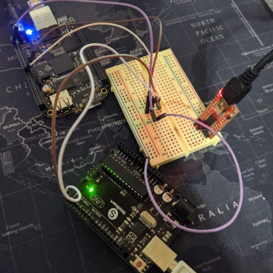
The complete source code for the Arduino application is in this project's repository. I am not going to cover it in detail, but it is thoroughly commented in the source code. The Arduino's serial transmit and receive pins (Pin 0 and Pin 1 on the Arduino UNO board) are connected to the corresponding UART 2 pins on the Beaglebone P9 header. I routed this connection to a bread board so I could replace either device with a USB-Serial adapter for debugging purposes.
The first step in creating the driver for the device outlined above is to add support for the defined messaging interface. First, an enumeration of the command IDs and a type to store them was defined
//Command ID enumeration
typedef enum CMD_ID_NUM
{
    LED_ON,
    LED_OFF,
    ADD,
    STATUS
}CMD_ID_NUM;

typedef unsigned char CMD_ID;
The additional type, CMD_ID is used to force the command ID represented in the enumeration to a 1-byte field.
Next, structures were added to represent each command:
//LED on and off command
typedef struct
{
    struct semaphore sem;
    union
    {
        struct
        {
            CMD_ID cmdId;
            unsigned char length;
        } fields;
        unsigned char data[2];
    } cmd;
    union
    {
        struct
        {
            CMD_ID cmdId;
            unsigned char length;
        } fields;
        unsigned char data[2];
    } resp;
}led_t;

//Add two numbers command
typedef struct
{
    struct semaphore sem;
    union
    {
        struct
        {
            CMD_ID cmdId;
            unsigned char length;
            unsigned char op1;
            unsigned char op2;
        } fields;
        unsigned char data[4];
    } cmd;
    union
    {
        struct
        {
            CMD_ID cmdId;
            unsigned char length;
            unsigned char sum;
        } fields;
        unsigned char data[3];
    } resp;
} add_t;
These structures contain two members, cmd and resp.
cmd - This member is used to represent the outgoing command messageresp - This member is updated with the resulting response from the device.sem - The semaphore used to signal that the command has been received.The purpose of the semaphore is described later in the post. It is provided in the semaphore.h file included in the top of the driver source. The led_t command type does not take additional parameters beyond the command ID and length. The add_t command type contains fields in the cmd structure to hold the operands. The add_t response structure contains a field for the resulting sum.
Similarly, a structure was defined for the asynchronous status messages.
//Async status messages
typedef struct
{
    struct semaphore sem;
    union
    {
        struct
        {
            CMD_ID cmdId;
            unsigned char length;
            unsigned char lastSum;
            unsigned char ledState;
        } fields;
        unsigned char data[4];
    } resp;
    int hasRx
} status_t;
resp - This member contains fields to hold the last calculated sum and the state of the LED, per the command interface description above.hasRx - This field is used to indicate that at least one status message has been received. This is used by the "get status" IOCTL later in this post.A structure was added to hold each command called cmd_list_t.
//Command list structure
typedef struct
{
    led_t ledOnCmd;
    led_t ledOffCmd;
    add_t addCmd;
    status_t statusMsg;
}cmd_list_t;
This structure was added to each instance of the device driver structure.
//Serial device struct
static struct hw_serial_dev
{
    void __iomem *regs;
    ...
    cmd_list_t cmdList;
    ...
};
Next a routine was added to initialize these commands when the device driver instance is initialized, called hw_init_commands.
static void hw_init_commands(struct hw_serial_dev * dev)
{
    //LED on
    dev->cmdList.ledOnCmd.cmd.fields.cmdId = LED_ON;
    dev->cmdList.ledOnCmd.cmd.fields.length = 0x0;
    sema_init(&dev->cmdList.ledOnCmd.sem, 0);

    //LED off
    dev->cmdList.ledOffCmd.cmd.fields.cmdId = LED_OFF;
    dev->cmdList.ledOffCmd.cmd.fields.length = 0x0;
    sema_init(&dev->cmdList.ledOffCmd.sem, 0);

    //Add command
    dev->cmdList.addCmd.cmd.fields.cmdId = ADD;
    dev->cmdList.addCmd.cmd.fields.length = 2;
    dev->cmdList.addCmd.cmd.fields.op1 = 0;
    dev->cmdList.addCmd.cmd.fields.op1 = 0;
    sema_init(&dev->cmdList.addCmd.sem, 0);

    //Status message
    dev->cmdList.statusMsg.hasRx = 0;
    sema_init(&dev->cmdList.statusMsg.sem, 1);
}
The argument to this routine is a pointer to an instance of the struct hw_serial_dev structure that contains the cmcd_list_t structure. Each command is initialized with the corresponding command ID, the length of data in each command, and default values for data fiels as needed. The status message hasRx field is set to 0 by default to indicate a status message has not been received yet. The command semaphores are initialized with an initial value of 0. The purpose of the semaphores is covered later in this post. This routine is called from the driver's probe routine once the struct hw_serial_dev has been allocated and initialized.
A routine called tx_and_wait was added that transmits a command and waits on the response before returning.
static int tx_and_wait(struct hw_serial_dev *dev, CMD_ID cmdId)
{
The first argument to this routine is a pointer to an instance of the device driver struct. The second argument is the ID of the command to send.
    unsigned char * ptr;
    unsigned int length;
    struct semaphore * sem;

    switch(cmdId)
    {
        case LED_ON:
        {
            ptr = dev->cmdList.ledOnCmd.cmd.data;
            length = sizeof(dev->cmdList.ledOnCmd.cmd.data);
            sem = &dev->cmdList.ledOnCmd.sem;
            break;
        }
        case LED_OFF:
        {
            ptr = dev->cmdList.ledOffCmd.cmd.data;
            length = sizeof(dev->cmdList.ledOffCmd.cmd.data);
            sem = &dev->cmdList.ledOffCmd.sem;
            break;
        }
        case ADD:
        {
            ptr = dev->cmdList.addCmd.cmd.data;
            length = sizeof(dev->cmdList.addCmd.cmd.data);
            sem = &dev->cmdList.addCmd.sem;
            break;
        }
        default: return -EINVAL;
    }
The switch statement at the top of the routine assigns the parameters to use for sending the command based on the command ID. The command pointer, ptr, is assigned to the command's data field. Notice that this field is unioned with the named fields on the given command. For example, on the add command, the data member contains the values assigned to the add command's cmd fields, cmdId, length, op1, and op2. Using this union technique allows the command to be constructed via named fields but transmitted as a generic array. The length field is calculated as the length of the command's data member. The semaphore pointer sem is assigned to the semaphore of the command being sent. If an invalid command ID is passed to this routine, a return value of EINVAL is returned.
    //Send the data bytes
    int i = 0;
    for(i = 0; i < length; i++)
    {
        write_char(dev, ptr[i]);
    }
    //Wait for TIMEOUT_SEC for the ACK semaphore
    unsigned long timeout = jiffies + TIMEOUT_SEC * HZ;
    while(jiffies <= timeout)
    {
        if(down_trylock(sem) == 0)
        {
            //Response received
            return 0;
        }
    }
    //Timed out waiting for response
    return -ETIMEDOUT;
}
The data is then transmitted by iterating over the command data using the ptr variable and sending each byte with the write_char routine. Once the command has been transmitted, the routine calculates a timeout period. The timeout uses the Linux kernel jiffies member, provided by jiffies.h included in the top of the file. This value is incremented in a platform-specific interval. Another parameter, HZ is provided that corresponds to jiffies-per-second. Using these two parameters, the number of jiffies corresponding to TIMEOUT_SEC seconds is calculated and stored in timeout. TIMEOUT_SEC is defined in the top of the file as 5 seconds.
Looping until jiffies exceeds timeout, the routine attempts to acquire the command semaphore. If the semaphore is signaled by the receive state machine (described below) then the routine returns successfully. If not, a value of -ETIMEDOUT is returned.
Once the external device receives the command from tx_and_wait, it will respond with an ACK message or the resulting data. The UART interrupt handler will handle this response by handing it off to an RX state machine that will reconstruct the serialized commands and carry out logic accordingly. In addition to command ACKs and responses, the state machine must also handle the asynchronous status messages.
First a structure is defined to hold RX state information.
typedef struct
{
    enum
    {
        RX_CMD,
        RX_LEN,
        RX_DATA,
        HANDLE
    }state;
    CMD_ID curCmd;
    int curLen;
    int mLen;
    unsigned char msg[4];
    int rxIdx;
    int msgIdx;
    int loop;
}rx_state_t;
state - This member contains the current state the RX state machine is incurCmd - This member contains the current command IDcurLen - This member contains the current data length of the commandmLen - This member tracks how many bytes remain to complete the current messagemsg - This member holds the body (data) of the current messagerxIdx - This member tracks the current index into the receive buffermsgIdx - This member tracks the current index into the message body bufferloop - This member is used to control the RX state machine while loopThe complete RX state machine code is in the repository for this project. It is outline in sections below.
static void handle_rx(struct hw_serial_dev * dev, unsigned int len)
{
    //Loop as long as we have data
    dev->rxStateVars.loop = 1;
    while(dev->rxStateVars.loop == 1)
The first argument to the handle_rx routine is a pointer to the device driver structure. The second argument, len is the number of bytes received when the handle_rx routine is called.
The loop state is set to 1. If the data received count is greater than 0, the state machine loop is entered. The first state is for receiving the command ID.
if(len > 0)
        {
            switch(dev->rxStateVars.state)
            {
                case RX_CMD:
                {
                    //Clear the message buffer, and receive the command
                    memset(dev->rxStateVars.msg, 0x0, sizeof(dev->rxStateVars.msg));
                    dev->rxStateVars.curCmd = dev->rxBuffer[dev->rxStateVars.rxIdx++];
                    len--;
                    dev->rxStateVars.state = RX_LEN;
                    if(len == 0)
                    {
                        //Break if no more data is available
                        dev->rxStateVars.loop = 0;
                        break;
                    }

                }
The message buffer is cleared with 0. The first byte in the receive buffer is the command ID. This is saved off into the state variable curCmd. The receive buffer index is incremented. The next state, receiving the command length (RX_LEN) is set. The length of data in the receive buffer is decremented. If no more bytes are available, the loop and state machine are broken. Otherwise, the state machine falls through into the next state.
case RX_LEN:
{
    //Receive the length of the UART command
    dev->rxStateVars.curLen = dev->rxBuffer[dev->rxStateVars.rxIdx++];
    dev->rxStateVars.mLen = dev->rxStateVars.curLen;
    len--;
    dev->rxStateVars.state = RX_DATA;
    if(len == 0 && dev->rxStateVars.curLen != 0)
    {
        //Break if no more data is available
        dev->rxStateVars.loop = 0;
        break;
    }
}
This next byte in the receive buffer is the current command length. This length is stored in the curLen and mLen state variables. curLen is intended to persist as the total length of the message. mLen is decremented as bytes are received to indicate when the entire message has arrived. The receive buffer index is incremented and the length decremented. The next state to receive the message body (RX_DATA) is set. If no more bytes are available, the loop and state machine are broken. Otherwise, the state machine falls through into the next state.
case RX_DATA:
{
    //Receive the data for the current command
    int bytes = dev->rxStateVars.mLen;
    if(bytes > len)
    {
        bytes = len;
    }
    //Copy the data into the message buffer
    memcpy(&dev->rxStateVars.msg[dev->rxStateVars.msgIdx],
        &dev->rxBuffer[dev->rxStateVars.rxIdx],
        bytes);
    dev->rxStateVars.mLen-= bytes;
    dev->rxStateVars.msgIdx += bytes;
    dev->rxStateVars.rxIdx += bytes;
    len-= bytes;
    if(dev->rxStateVars.mLen == 0)
    {
        //If the whole message has been received,
        //handle it.
        dev->rxStateVars.state = HANDLE;
    }
    else
    {
        if(len == 0)
        {
            //Break if no more data is available
            dev->rxStateVars.loop = 0;
            break;
        }
    }
}
The RX_DATA state is used to copy the message body from the receive buffer into the state message buffer variable. The logic at the top of the state is used to ensure that only the correct amount of data is copied into the message buffer. If the data available exceeds the number of bytes required by the message, the copy operation is limited to just the bytes needed. If the number of bytes needed exceeds the number of bytes available, all of the available bytes are copied. The mLen member is decremented by the number of bytes copied. The message index, msgIdx, is incremented accordingly. The index into the receive buffer is also incremented, and the number of bytes available decremented. If msgLen is 0, indicating that the entire message has been received, the "handle message" (HANDLE) state is entered. Otherwise, if no more data is available, the state machine and loop are broken. Subsequent calls to the state machine will continue to populate the message buffer until the entire message has been received and the "handle message" state is entered.
The "handle message" state contains a switch on the current command ID. The first case handles the LED_ON ACK message
case HANDLE:
{
    //Handle the current message
    switch(dev->rxStateVars.curCmd)
    {

        case LED_ON:
        {
            up(&dev->cmdList.ledOnCmd.sem);
            break;
        }
This ACK message does not contain any actionable data, so the only required action is to signal the command semaphore. This allows the tx_and_wait routine to acquire the LED_ON command semaphore, indicating that the response to the LED_ON command has been received. The next case is the LED_OFF command.
        case LED_OFF:
        {
            up(&dev->cmdList.ledOffCmd.sem);
            break;
        }
This case is identical to the LED_ON case but operates on the LED_OFF command semaphore.
The next case is for the response to the ADD command.
        case ADD:
        {
            spin_lock_irqsave(&dev->lock, dev->irqFlags);
            //Copy the command response into the response object
            dev->cmdList.addCmd.resp.fields.cmdId = ADD;
            dev->cmdList.addCmd.resp.fields.length = 1;
            dev->cmdList.addCmd.resp.fields.sum = dev->rxStateVars.msg[0];
            spin_unlock_irqrestore(&dev->lock, dev->irqFlags);
            up(&dev->cmdList.addCmd.sem);
            break;
        }
First, the mutex on the device structure is locked so that a userpsace program can't read the response (via IOCTL, covered below) while the driver is populating it, and vice versa. Next, the response fields are populated with the response from the external device; specifically, the command ID of ADD, the length of 1 and the sum of the operands. The device mutex is unlocked and the ADD command semaphore is signaled.
The next case handles the asynchronous status messages.
        case STATUS:
        {
            spin_lock_irqsave(&dev->lock, dev->irqFlags);
            //Copy the command response into the response object
            dev->cmdList.statusMsg.resp.fields.cmdId = STATUS;
            dev->cmdList.statusMsg.resp.fields.length = 2;
            dev->cmdList.statusMsg.resp.fields.lastSum = dev->rxStateVars.msg[0];
            dev->cmdList.statusMsg.resp.fields.ledState = dev->rxStateVars.msg[1];
            dev->cmdList.statusMsg.hasRx = 1;
            spin_unlock_irqrestore(&dev->lock, dev->irqFlags);
            break;
        }

    }
This case operates similarly to the ADD case. The status information (led state and previously calculated sum) is copied to the command response structure. The status message hasRx field is set to indicate at least one status message has been received. The command semaphore is not signaled here because this message was not in response to a command sent from tx_and_wait. The semaphore was left in to handle the case where an IOCTL may request to wait on an asynchronous status message; however, this was not implemented in this driver.
Lastly, the State machine does some cleanup for the next message.
    //Reset the state machine for the next message
    dev->rxStateVars.state = RX_CMD;
    dev->rxStateVars.msgIdx = 0;
    if(len == 0)
    {
        //Break if no more data is available
        dev->rxStateVars.loop = 0;
    }
    break;
}
The state is returned to the "receive command" state (RX_CMD), the message buffer index is reset to 0. If there is still available data in the buffer beyond the data required for the current message, it indicates that there is another message to process. Otherwise, if no data is available, the loop and state machine are broken.
The final line of the state machine resets the receive buffer index.
//Reset the receive buffer index
dev->rxStateVars.rxIdx = 0;
This line is reached every time the state machine loop is broken, indicating that the state machine has consumed all of the data available in the UART receive buffer.
Now that the driver supports the asynchronous messaging interface, a userspace application will need some means of exercising the commands. This is handled through IOCTL calls. IOCTL, a portmanteau of "IO Control", calls are essentially driver-specific system calls. The IOCTL calls operate on the file descriptor for the device driver entry in the dev directory. IOCTL calls consist of an IOCTL identifier and can accept an arbitrary data structure pointer. The IOCTL identifier is constructed of a driver-specific, globally unique "magic" number combined with a driver-scope unique IOCTL number used to distinguish different IOCTL available on a given driver. More information about IOCTL calls is available in the Linux man pages..
Macros are used to construct IOCTL identifiers that are provided by the ioctl.h file. This file will be included both in the driver and in the userspace application. These IOCTL identifiers and associated data structures are require by both the driver and any userspace applications that will call them. A header file was created to hold these parameters called hw_ioctl.h.
The first lines of the file define the IOCTL numbers the driver will support.
//This type enumerates the IOCTL numbers
typedef enum
{
    LED_ON_IOCTL_NUM = 0xA,
    LED_OFF_IOCTL_NUM,
    ADD_IOCTL_NUM,
    GET_STATUS_IOCTL_NUM
} HW_IOCTL_ID;
An IOCTL number is added for each of the operations that the external device supports, "Led on", "Led off", and "add two numbers". Another IOCTL number is added that will be used to request the latest status information the driver received asynchronously.
Next, data structures that will be passed (as pointers) to the driver when the IOCTLs are called are defined.
//This type defines the data structure for the status
//IOCTL call
typedef struct
{
    char lastSum;
    char ledStatus;
} hw_ioctl_status_t;
The first, hw_ioctl_status_t, contains fields that the driver will populate with the status information.
lastSum - The previous sum calculated by the external deviceledStatus - The state of the LED (on (1), or off (0)) at the time that the last status message was sent//This type defines the data structure for the add
//IOCTL call
typedef struct
{
char numA;
char numB;
char sum;
} hw_ioctl_add_t;
The hw_ioctl_add_t type contains two field for the userpsace application to populate with operands for the "add two numbers" command, and a field that the driver will populate.
numA - the first operandnumB - the second operandsum - the sum of the two numbers calculated by the external deviceThe "led on" and "led off' functionality do not require data structures.
Next, an IOCTL "magic" number is chosen.
//The IOCTL magic for the driver
#define HW_IOCTL_MAGIC 0x249
This number is arbitrary, but it must be globally unique within the kernel. If it isn't, the IOCTL identifier generated for the given magic number+IOCTL number combination will end up associated with two different, unrelated drivers. The standard Linux kernel source tree contains a document,
documentation/ioctl/ioctl-number.txt which contains a list of reserved IOCTL magic numbers. For a "real" driver, an IOCTL magic number must be reserved here when a pull request is made to the kernel.
The kernel provides macros to create IOCTL identifiers. It is best practice to utilize these macros rather than directly encoding the IOCTL identifier. More information about that is available in documentation/ioctl/ioctl-decoding.txt. The following lines in the hw_ioctl.h file create the IOCTL identifiers for each IOCTL.
//LED on IOCTL
#define HW_IOCTL_LED_ON _IO(HW_IOCTL_MAGIC, LED_ON_IOCTL_NUM)

//LED off IOCTL
#define HW_IOCTL_LED_OFF _IO(HW_IOCTL_MAGIC, LED_OFF_IOCTL_NUM)

//Add IOCTL
#define HW_IOCTL_ADD _IOWR(HW_IOCTL_MAGIC, ADD_IOCTL_NUM, hw_ioctl_add_t)

//Status IOCTL
#define HW_IOCTL_GET_STS _IOR(HW_IOCTL_MAGIC, GET_STATUS_IOCTL_NUM, hw_ioctl_status_t)
#endif
The macros above take the IOCTL magic number as the first argument, the IOCTL number as the second, and, in some cases, a data type. The data type parameter is used to calculate the size of the memory to which the IOCTL pointer argument points.
The HW_IOCTL_LED_ON and HW_IOCTL_LED_OFF IOCTLs both use the _IO macro. This indicates that no data is passed from userspace to the kernel. As such, they do not require a type argument. The HW_IOCTL_ADD IOCTL uses the _IOWR macro, indicating that data is passed both from userspace to the kernel (the add operands), and from the kernel to userspace (the resulting sum). Finally, the HW_IOCTL_GET_STS IOCTL uses the _IOR macro, indicating that the userpsace application will read data from the kernel (the status data). These two macros take type arguments, hw_ioctl_ad_t and hw_ioctl_status_t respectively. In reality, all of these macros encode a an IOCTL identifier that is agnostic to the data transfer operations; however, best practice is to use them as described in the ioctl-decoding.txt documentation linked above.
These definitions will allow the userspace program to call the ioctl system call (covered below) and allow the driver to associate with and handle these calls. First, the file operations structure is modified.
//File operations struct
static const struct file_operations hw_fops = {
    .owner = THIS_MODULE,
    .open = hw_open,
    .release = hw_close,
    .llseek = no_llseek,
    .unlocked_ioctl = unlocked_ioctl
};
A routine was added to the driver's file_operations.unlocked_ioctl field. Because the driver is no longer a generic UART read/write driver, the read and write operations were removed from the file_operations and from the source code. This ensures that the userspace application must interact with the external device via the specified IOCTL calls.
The unlocked IOCTL routine is called by the kernel whenever an IOCTL identifier corresponding to this driver is called on it's file handle.
long unlocked_ioctl(struct file *file, unsigned int cmd, unsigned long argp)
{
    struct miscdevice *mdev = (struct miscdevice *)file->private_data;
    struct hw_serial_dev *dev = container_of(mdev, struct hw_serial_dev, mDev);
The first argument to this routine is the pointer to the file handle corresponding to the device driver, file. The next argument, cmd is the IOCTL number. The final argument, p, is the pointer to the IOCTL data structure, if any. The required signature for this routine is defined in the file_operations structure in fs.h.
The first two lines of the of the routine use the container_of macro to get a pointer to the device's hw_serial_dev structure.
Next, a switch statement is used to handle each supported IOCTL command via the IOCTL number.
 switch(cmd)
    {
        case LED_ON_IOCTL_NUM:
        {
            //Turn on the LED
            return (long)tx_and_wait(dev, LED_ON);
        }
The first case handles the "led on" IOCTL. The only operation is to call the tx_and_wait routine outlined above. If the command succeeds, a value of 0 will be returned to indicate success. Otherwise, a value of -ETIMEDOUT will be returned indicating the command timed out.
The next case handles the "led off" IOCTL.
case LED_OFF_IOCTL_NUM:
{
    //Turn off the LED
    return (long)tx_and_wait(dev, LED_OFF);
}
This case is identical to the "led on" case, but calls tx_and_wait with the LED_OFF command ID. The next case handles the "add two numbers" IOCTL.
case ADD_IOCTL_NUM:
        {
            //Add two numbers
            hw_ioctl_add_t * user = (hw_ioctl_add_t*) argp;
            hw_ioctl_add_t kuser;
            if( copy_from_user(&kuser, user, sizeof(hw_ioctl_add_t) ) )
            {
                return -EFAULT;
            }
            dev->cmdList.addCmd.cmd.fields.op1 = kuser.numA;
            dev->cmdList.addCmd.cmd.fields.op2 = kuser.numB;
            if(tx_and_wait(dev,  ADD) != 0)
            {
                //Timed out waiting for the response
                return -ETIMEDOUT;
            }
            spin_lock_irqsave(&dev->lock, dev->irqFlags);
            kuser.sum = dev->cmdList.addCmd.resp.fields.sum;
            spin_unlock_irqrestore(&dev->lock, dev->irqFlags);
            if( copy_to_user(user, &kuser, sizeof(hw_ioctl_add_t) ) )
            {
                return -EFAULT;
            }
            return 0;
        }
The first operation in this case is to cast the pointer argument to the type associated with the "add" IOCTL, hw_ioctl_add_t. This pointer points to userpsace memory, so a kernelspace instance is created and the copy_from_user routine is used to transfer the data. If this operation fails, a failure code of -EFAULT is returned. Next, the device's "add" command is populated with the operands passed by the userspace application. tx_and_wait is called with the ADD command id. If the command times out, an error code of -ETIMEDOUT is returned. If the command succeeds, the device mutex is locked and the resulting sum is copied out of the device "add" command response into the kernelspace IOCTL data structure. Next, the resulting sum is copied from the kernelspace data structure to the userspace data structure using the copy_to_user routine. If the copy fails, the error code of -EFAULT is returned, otherwise 0 is returned to indicate the operation was successful. The last case handles the "get status" IOCTL.
        case GET_STATUS_IOCTL_NUM:
        {
            hw_ioctl_status_t * user = (hw_ioctl_status_t*) argp;
            hw_ioctl_status_t kuser;
            spin_lock_irqsave(&dev->lock, dev->irqFlags);
            kuser.lastSum = dev->cmdList.statusMsg.resp.fields.lastSum;
            kuser.ledStatus = dev->cmdList.statusMsg.resp.fields.ledState;
            int rx = dev->cmdList.statusMsg.hasRx;
            spin_unlock_irqrestore(&dev->lock, dev->irqFlags);
            if(rx == 0)
            {
                //We haven't received a status message yet
                return -ENODATA;
            }
            if( copy_to_user(user, &kuser, sizeof(hw_ioctl_status_t) ) )
            {
                return -EFAULT;
            }
            return 0;
        }
        default:
            return -EINVAL;
    }
}
First, the userspace pointer is cast to the correct type for this IOCTL, hw_ioctl_status_t. Next, a kernel space instance of this type is created. The device structure mutex is locked and the kernelspace data structure is populated with the data in the device structure's status message response field. The value of the hasRx field is saved off. Next, if the hasRx flag indicates that a status message has not been received yet, an error code of -ENODATA is returned. If a status message has been received, the data is copied from the kernelspace data structure to the userspace data structure. If this operation fails, an error code of -EFAULT is returned. Otherwise, 0 is returned to indicate that the IOCTL was successful.
The default case indicates that an invalid IOCTL number was called by returning an error code of -EINVAL.
The driver can now be compiled, installed, and run as described in the previous post linked at the top of this page.
The driver's IOCTL calls can now be used by a userspace application to control and interact with the external device. A simple driver program was written to exercise the functionality.
This userspace application must include the IOCTL definitions in hw_ioctl.h and ioctl.h from the Linux kernel. Routines were added to exercise each IOCTL call.
//Turn the LED on or off
void ioctl_led(int fd, int on)
{
    int ret;
    if (on == 1)
    {
        //Call the "led on" IOCTL
        ret = ioctl(fd, LED_ON_IOCTL_NUM, 0);
        if (ret != 0)
        {
            printf("Led on failed: %d\n", ret);
        }
        else
        {
            printf("Led on success.\n");
        }
    }
    else
    {
        //Call the "led off" IOCTL
        ret = ioctl(fd, LED_OFF_IOCTL_NUM, 0);
        if (ret != 0)
        {
            printf("Led off failed: %d\n", ret);
        }
        else
        {
            printf("Led off success.\n");
        }
    }
}
This ioctl_led routine's first argument is the file handle corresponding to the device driver. The second argument is a flag indicating if the LED should be turned on (1) or off (0). If the call is made with the on argument set to 1, the "led on" IOCTL is called. This is done with the ioctl function call provided in ioctl.h. The first argument is the file handle, the second is the IOCTL number, and the final argument is the data pointer. Recall that the IOCTL number, LED_ON_IOCTL_ON, is defined in hw_ioctl.h and used in the construction of the "led on" IOCTL identifier by the IOCTL macro. The final pointer argument is 0 because the "led on/off" IOCTL calls do not pass or receive data to/from the kernel. If the IOCTL call succeeds, a return value of 0 is received from the driver. Otherwise, an error code is received and printed.
The else case above is the corresponding call to the "led off" IOCTL.
The next routine exercises the "add two numbers" functionality.
//Add two numbers
void ioctl_add(int fd, unsigned char numA, unsigned char numB)
{
    //Populate the command structure with the values to add
    hw_ioctl_add_t add;
    add.numA = numA;
    add.numB = numB;

    //Call the "add" IOCTL
    int ret = ioctl(fd, ADD_IOCTL_NUM, &add);

    if (ret != 0)
    {
        printf("Add failed: %d\n", ret);
    }
    else
    {
        //Print the SUM returned by the device
        printf("Add success, sum: %d.\n", add.sum);
    }
}
The arguments to this routine are the file descriptor and the two ADD operands, numA and numB. A hw_ioctl_add_t data structure is populated with the operands. Recall this data structure is defined in hw_ioctl.h and was used to create the IOCTL identifier via the IOCTL macros. The kernel-side of the IOCTL is expecting that the pointer argument to the ioctl call will be of this data type. The file descriptor, the "add" IOCTL number and the pointer to the data structure are passed to the ioctl call. If this call returns 0 to indicate success, the data structure will have been populated by the kernel-side of the IOCTL with the resulting sum. This sum is printed to the console. If a non-zero error message is returned, it indicates that the command failed, and the error code is printed.
The next routine handles the "get status" IOCTL.
//Query the latest asynchronous status message
void ioctl_get_status(int fd)
{
    //Call the IOCTL with the status structure
    hw_ioctl_status_t stat;
    int ret = ioctl(fd, GET_STATUS_IOCTL_NUM, &stat);
    if(ret != 0)
    {
        printf("Status failed: %d\n", ret);
    }
    else
    {
        //Print the information sent by the device
        printf("Status success, last sum: %d led state: %d\n",
               stat.lastSum, stat.ledStatus);
    }

}
Similar to the "add" IOCTL, this routine creates a hw_ioctl_status_t instance and passes it to the kernel. The IOCTL handler in the device driver will populate this structure with the status data and return a success code. If the status IOCTL fails, or a status message hasn't been received from the device yet, a failure code is returned and will be printed to the console. The data from a successful call will be printed to the console.
The body of the program handles opening the device driver's file descriptor and calling the above routines on it.
void main()
{
    //Open the driver's device entry file
    int fd;

    fd = open("/dev/hw_serial-48024000", O_RDWR);

    if (fd < 0)
    {
        printf("File open error\n");
    }
A call to open is made, passing the path to the device driver's file entry and the O_RDWR flag indicating read/write mode. If a negative value
is returned by this call, the file could not be opened. Next, the program exercises the IOCTL calls.
    //Turn the LED on
    ioctl_led(fd, 1);

    //Wait a little while for an asynchronous status message
    sleep(4);

    //Query the latest status update
    ioctl_get_status(fd);

    //Blink the LED
    for(int i = 0; i < 3; i++)
    {
        //Turn the LED ON
        ioctl_led(fd, 1);
        sleep(1);

        //Turn the LED off
        ioctl_led(fd, 0);
        sleep(1);

    }

    //Add two numbers
    ioctl_add(fd, 5, 7);

    //Query the status again
    ioctl_get_status(fd);

    //Close the driver's device file
    close(fd);
}
This program turns the LED on, waits briefly for an asynchronous status message to arrive (with no guarantee that one will arrive), then prints the resulting status information. Next the program loops, blinking the LED on and off for one second at a time, three times. After that, a request is sent to the device to add the numbers 5 and 7. If this operation succeeds, the sum is printed. Lastly, another request is made to query the most recent status message, the result of which is printed. Finally, the file descriptor is closed.
The userspace application must run on the Beaglebone Black. The easiest way to compile this application is by first transferring the source files to the Beaglebone using SCP, then compiling them natively on the Beaglebone using GCC. I prefer to cross-compile my applications on my PC and then transfer the pre-built executable to the Beaglebone. I will briefly cover the steps needed to set up this type of cross-compilation environment in Ubuntu Linux. These steps are specific to my compilation environment. If you are attempting to set a similar environment up on a different platform, a quick google search of "Cross compile for Beaglebone Black on
First, I added the Ubuntu "ports" package list to my apt sources by modifying the /etc/apt/sources.list file. The following line was added at the end of the file. Notice the use of the armhf architecture.
deb [arch=armhf] http://ports.ubuntu.com/ trusty main universe
All other pre-existing entries in this file were updated to explicitly specify the correct architecture for my machine. This step is important!! for example:
deb [arch=amd64] http://us.archive.ubuntu.com/ubuntu/ bionic main restricted
I updated my package repositories using the command:
sudo apt-get update
Next, I added the armhf architecture to my Ubuntu machine, using the command:
sudo dpkg --add-architecture armhf
The following command should now list armhf as an architecture:
sudo dpkg --print-foreign-architectures
Next the cross-compilation toolset for armhf can be installed with the following command:
apt-get install crossbuild-essential-armhf
Finally, the userpsace application can be built using the following command (I put mine in a Makefile in the same directory as the source code):
arm-linux-gnueabihf-gcc hw_ioctl_user.c -o hw_ioctl_user
Running the Linux utility "file" on the file results in output that lists ld-linux-armhf.so as the linker:
hw_ioctl_user: ELF 32-bit LSB shared object, ARM, EABI5 version 1 (SYSV), dynamically linked, interpreter /lib/ld-linux-armhf.so.3
This application can be copied to the Beaglebone using SCP and executed from the command line in an SSH session. The following images show the output from this application and the resulting LED state changes on the Arduino board (these aren't necessarily synchronized).
This post covered one possible approach to a UART messaging interface and a technique for creating a device-specific driver that can be controlled via the IOCTL mechanism. This post wraps up my experimentation with creating Linux device drivers that I began in my previous two posts. Although this driver is for a simulated device and far from robust, the development process provides introductory information and skills applicable to a "real" driver development project.