This post is a continuation of the previous one here. Throughout this post, I use the same build environment and linux kernel repository as that post. I'm going to cover (in great detail) the development and testing of a simple UART driver on the Beaglebone Black. The source code and device tree files for this project are in the repository linked above.
The first step for creating a custom device driver is creating the device itself. A device tree is a data structure that contains information about devices present on a given system. The device tree source is written in Device Tree Source (DTS) files and compiled into a Device Tree Binary (DTB). The Linux kernel can access this data structure to obtain information about physical devices attached to the system.
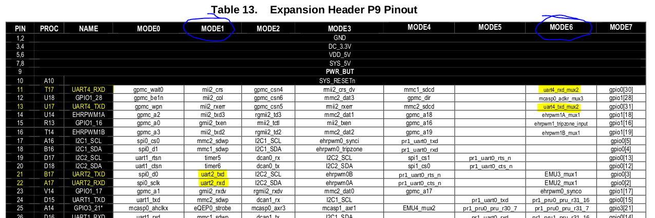
The Beaglebone black uses a Texas Instruments Sitara AM335 processor that provides six UARTs. Per the Beaglebone Black System Reference Manual, UART2 and UART4 are attached to the P9 expansion header. Table 13 in the reference manual shows the pin multiplexing mode needed to enable the UARTs, mode 2 and mode 6 for UART2 and UART4 respectively. This configuration can be encoded into the DTB file. This table also shows the corresponding pins on the P9 header. Lastly, the table shows the corresponding processor pin names (See the highlighted portions of the image below).
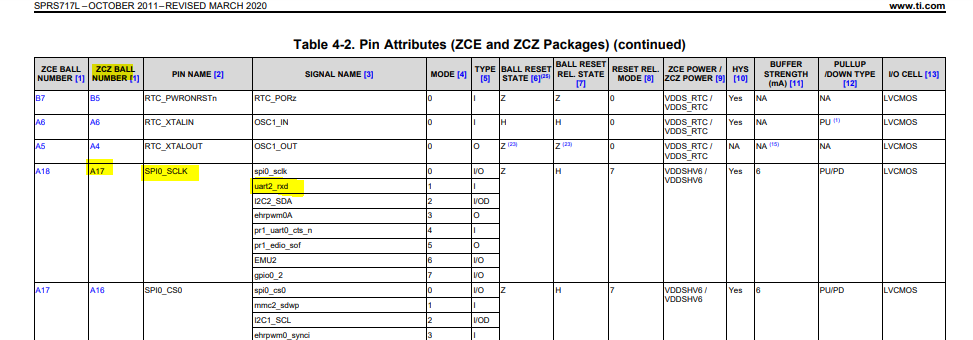
The processor datasheet contains a Pin Attributes section that contains the pin names corresponding the processor pin number. For example the UART2 receive pin, processor pin A17, is named SPI0_SCLK.
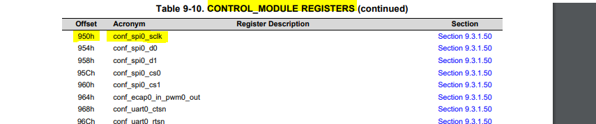
The processor technical reference manual CONTROL_MODULE registers section contains the pin multiplexing control offset for SPI0_SCLK: 0x950.
Putting this information together for all of the UART pins results in the following pin configuration:
| Pin | Header Pin | Processor Pin | Processor Pin Name | Mux Control Offset |
|---|---|---|---|---|
| UART 2 RX | 22 | A17 | SPI0_CLK | 0x950 |
| UART 2 TX | 21 | B17 | SPI0_D0 | 0x954 |
| UART 4 RX | 11 | T17 | GPMC_WAIT0 | 0x870 |
| UART 4 TX | 13 | U17 | GPMC_WPn | 0x874 |
This information is sufficient to create device tree entries for the UART devices. Make a mental note where this pin-out is, because the header pins will be used to hook up a serial device to test the driver.
A Device Tree Source file (.dts) can be added to the linux/arch/arm/boot/dts/ directory with a descriptive name; in this example it is am335x-bonecustom.dts. Documentation of the device tree language can be found here. It is useful to reference the existing device tree files already in the Beaglebone repository. The following section shows the contents of the device tree source file. It is commented with descriptions of the entries.
/* This line includes the existing Beaglebone Black
Device Tree Source file so portions can be overridden */
#include "am335x-boneblack.dts"
/* This label, am335xx_pinmux, refers to the existing pin muxing
definition found in the am33xx.dtsi include file. */
&am33xx_pinmux {
	uart2_pins: uart2_pins { //This section adds muxing for UART2
		/*
        pinctrl-single,pins means the pin does not support generic pin configuration
        and that the muxing register is 1 byte wide.

        The AM33XX_IOPAD macro comes from omap.h. It provides the absolute physical
        address of the given address, as opposed to an offset from the base of the register.

        The first argument is the address obtained from the processor technical reference manual.

        The PIN_OUTPUT_PULLDOWN flag indicates that the pin should be pulled low,
        and the MUX_MODE1 flag indicates pin muxing mode 1 should be used. (per the Beaglebone
        system reference manual)
        */
        pinctrl-single,pins = <
			AM33XX_IOPAD(0x954, PIN_OUTPUT_PULLDOWN | MUX_MODE1)
			AM33XX_IOPAD(0x950, PIN_INPUT_PULLUP | MUX_MODE1)
			>;
	};

    //A similar definition is added to for UART4
	uart4_pins: uart4_pins {
	pinctrl-single,pins = <
		AM33XX_IOPAD(0x870, PIN_INPUT_PULLUP | MUX_MODE6)
		AM33XX_IOPAD(0x874, PIN_OUTPUT_PULLDOWN | MUX_MODE6)
		>;
	};
};

/*
The label here references the device defined in the am33xx.dtsi include file.
The fields populated here will override those in the original definition.
*/
&uart2 {
	compatible = "serial"; //This is used when identifying a compatible device driver
	status = "okay"; ///Setting the status to "okay" enables the device
    //This is the name that corresponds to the pin control mode on the line below it
	pinctrl-names = "default";
    //This last entry binds the UART2 device to the pin control node defined above
	pinctrl-0 = <&uart2_pins>;
};

//A similar entry is created for the UART4 device.
&uart4 {
	compatible = "serial";
	status = "okay";
	pinctrl-names = "default";
	pinctrl-0 = <&uart4_pins>;
};
This file can be compiled into a binary data structure called a flattened Device Tree Binary/Blob (DTB). This binary is loaded into nonvolatile memory and provided to the kernel by the boot loader. The following Make target in the Linux repository will build all of the DTBs:
make dtbs
The DTB file can be found in linux/arch/arm/boot/dts.
The next step is to deploy this DTB alongside the kernel. My previous post describes the process of building and deploying a custom kernel on the Beaglebone Black. The process is the same as I documented in the Deploy the kernel section of that post, except the default DTB is replaced with the newly created DTB.
The device driver is created in the form of a loadable kernel module. There are plenty of good sources (see the references section at the end of this post) for building a "hello world" kernel module, so I'll only cover it briefly. I built my kernel module "out of tree", i.e. not in the Linux kernel tree. Other setup information about the build environment is in the previous post.
The first step is to create a folder to hold a Makefile and a source file for the kernel module. My directory structure looks like this:
.
├── kmodules
│   ├── hw_serial.c
│   ├── Makefile
├── linux
│   ├── arch
│   │── block
│   │── ...
Assuming the same directory structure and source code file name, a minimal Makefile would be as follows:
```
obj-m := hw_serial.o
KDIR := ../linux
all:
    $(MAKE) -C $(KDIR) M=$(PWD)
```
obj-m := hw_serial.o - This object file will be built from the source file of the same name and linked into a .ko module by the kernel build system.KDIR := ../linux - This argument points to the location of the linux source tree to build against$(MAKE) -C $(KDIR) M=$(PWD) - This command runs Make in the current directory against the linux source tree to build and link the kernel module.I will cover building and deploying the kernel module later in this post.
This section will provide a breakdown of a minimalist serial driver used for the newly added UART devices. It does not make use of the Linux serial framework. I will cover each portion of code and gradually build up to the complete source file. I feel that is the best format to make the code more digest-able. The complete code is available in the repository linked at the top of this post. I use the prefix hw_ frequently throughout the file. This was just the naming convention I chose (It stands for "hello world"). I also used generic names and values in other portions of the code, I will point out which ones are significant to functionality and which are just arbitrary names.
The basic life-cycle of the driver is summarized below. Each of these stages will be covered in detail from a source code perspective.
The kernel module begins with a set of necessary includes. I will cover each of them and why they are needed as I go, but for now, here is the include list at the top of the file:
    #include <linux/miscdevice.h>
    #include <linux/fs.h>
    #include <linux/kernel.h>
    #include <linux/module.h>
    #include <linux/serial_reg.h>
    #include <linux/of.h>
    #include <linux/io.h>
    #include <linux/pm_runtime.h>
    #include <linux/platform_device.h>
    #include <linux/init.h>
    #include <linux/uaccess.h>
    #include <linux/irqreturn.h>
    #include <linux/wait.h>
    #include <linux/interrupt.h>
    #include <linux/spinlock.h>
The bare minimum kernel module components are an initialization routine and an exit routine. This driver will utilize a framework provided by the Linux kernel called a Platform Driver. A macro is used to register the platform driver that removes the need for some of the boilerplate kernel module code. I will cover that below. There are macros for providing information about the kernel module such as description, version, author etc. I only made use of author and license.
Loading proprietary, closed-source licensed, and out-of-tree modules will generate a "tainted kernel" warning. Additionally, some kernel routines are conditionally exported for use exclusively by loadable modules that use a GNU General Public (GPL) compatible license.* Routines that this driver relies on fall into this category.
*This information was omitted in a previous version of this post and was since added thanks to the Twitter user @pypebros who pointed it out.
The following two lines are added at the bottom of the source code. The latter declares that this module is licensed under GPL. They are provided by the included module.h file:
MODULE_AUTHOR("Alex Rhodes");
MODULE_LICENSE("GPL");
The outermost layer of the serial driver is a Linux platform driver. The platform driver structure is registered with the kernel and provides function pointers to carry out operations required by the Linux driver model conventions. The structure is defined in the included file platform_device.h and declared as follows:
//Platform driver structure
static struct platform_driver hw_plat_driver = {
    .driver = {
        .name = "serial",
        .owner = THIS_MODULE,
        .of_match_table = hw_match_table
    },
    .probe = hw_probe,
    .remove = hw_remove
};
.driver - This member is the Linux driver structure of type struct device_driver.
.name - This is an arbitrary name given to the driver. I chose a generic name, "serial"..owner - This field specifies the module that owns the driver. The macro THIS_MODULE indicates that this module is the owner..of_match_table - This field specifies the open firmware match table, used to match devices in the device tree to compatible drivers. It is covered below..probe - This is the pointer to the probe routine. Probe is is called by the kernel to identify the existence of a given device and bind its compatible driver..remove - This routine is called to carry out any cleanup needed when a driver for a given device or the device itself is removed.I will cover the probe and remove routines later in this post, just make note of the fact that they are provided to the platform device so the kernel can utilize them as needed.
The of_match_table structure is an array of of_device_id objects that are defined in the included of.h file. It is used to pair drivers with their compatible devices. The structure is declared as:
static struct of_device_id hw_match_table[] =
    {
        {
            .compatible = "serial",
        },
};
.compatible string. This string matches with the compatible field in the device tree data structure defined above. These fields can be an arbitrary string, but they must match or the kernel will not match the driver with its device.The previous two data structures (and related routine implementations) are the components of a bare-bones Linux platform driver. If custom init and exit routines are needed, the kernel module and the platform driver must be registered with the kernel manually. Otherwise, there is a macro that simplifies the process and removes the need to write a bunch of boilerplate code. The macro takes the platform driver object as an argument. It is placed at the bottom of the file:
//Register the platform driver
module_platform_driver(hw_plat_driver);
A module-defined (i.e. not a kernel structure) structure is needed to encapsulate various parameters of the driver. It is declared as follows:
//Serial device struct
struct hw_serial_dev
{
    void __iomem *regs;
    struct miscdevice mDev;
    int irq;
    struct circ_buff buf;
    wait_queue_head_t waitQ;
    spinlock_t lock;
    unsigned long irqFlags;
};
The fields and their purpose will be described in detail below, but briefly:
void __iomem *regs - This field is a void pointer that will hold the base address of the control registers for the UART devices. The __iomem macro is used by a semantic checking tool called Sparse. This kernel module is not compiled with the Sparse flag, so this macro is ignored, but it is included as a best practice. More information about this parameter is detailed in this Stackoverflow answer.struct miscdevice mDev - This field holds a miscdevice. This is a very thin framework used to facilitate the implementation of "miscellaneous" devices, i.e. a driver that doesn't fit into other frameworks provided by the kernel. It's important to note that a "real" serial driver would use the Linux serial driver framework, but this minimalist driver does not. The miscdevice framework is provided by the miscdevice.h include file.int irq - This field will hold the IRQ number.struct circ_buff buf - This is a very simplistic circular buffer for holding received bytes.wait_queue_head_t waitQ - This object allows for callers to wait for data when reading from the driver.spinlock_t lock - This object is used for mutual exclusion of shared resourcesunsigned long irqFlags - This field stores whether interrupts are enabled or disabled when lock is locked so the state can be restored when lock is unlocked.A basic ring buffer is used to hold bytes as they are received before they are read by a program using the driver.
//Circular buffer struct
struct circ_buff
{
    char buff[BUFF_SIZE];
    int read_pos;
    int write_pos;
    int length;
};
char buff[BUFF_SIZE] - A byte buffer of size BUFF_SIZE, defined at the top of the file: #define BUFF_SIZE 512.int read_pos - The current offset in the ring buffer to read from.int write_pos - The current offset in the ring buffer to write to.int length - This parameter keeps track of how many characters are in the bufferThere are two utility methods for reading and writing to/from the ring buffer:
void write_circ_buff(char c, struct hw_serial_dev *dev)
{
    spin_lock_irqsave(&dev->lock, dev->irqFlags);
   if(dev->buf.length < BUFF_SIZE)
    {
        dev->buf.buff[dev->buf.write_pos] = c;
        dev->buf.write_pos = ((dev->buf.write_pos + 1) % BUFF_SIZE);
        dev->buf.length++;
    }
    spin_unlock_irqrestore(&dev->lock, dev->irqFlags);
}

/*********************************************************/
char read_circ_buff(struct hw_serial_dev *dev)
{
    spin_lock_irqsave(&dev->lock, dev->irqFlags);
    char c = dev->buf.buff[dev->buf.read_pos];
    dev->buf.buff[dev-> buf.read_pos] = '\0';
    if(dev->buf.length > 0)
    {
        dev->buf.buff[dev->buf.read_pos] = '\0';
        dev->buf.read_pos = ((dev->buf.read_pos + 1 ) % BUFF_SIZE);
        dev->buf.length--;
    }
    spin_unlock_irqrestore(&dev->lock, dev->irqFlags);
    return c;
}
These functions take a pointer to the hw_serial_dev structure that contains the ring buffer and a spinlock. The spinlock object is provided in the included spinlock.h file. The mechanism is a simple mutex that prevents concurrent access to the ring buffer. This is necessary because the driver may be receiving bytes from a connected device and placing them into the buffer while a program is attempting to read bytes from the buffer.
read_circ_buff reads a byte if there is one available, sets that position to null, and returns it.
write_circ_buff takes a byte as an argument and, if there is space, writes it into the circular buffer.
It is important to note that if bytes are not read fast enough, newly received bytes will be dropped. Additionally, if read is called when the buffer is empty, it will return the null character '\0'.
A structure containing pointers to routines related to common Linux file operations is provided for the miscdevice framework. The implementation of these methods and the purpose of this structure will be covered in detail later in this post.
//File operations struct
static const struct file_operations hw_fops = {
    .owner = THIS_MODULE,
    .read = hw_read,
    .write = hw_write,
    .open = hw_open,
    .release = hw_close,
    .llseek = no_llseek,
};
owner - This member is the owner of the structure, in this case the THIS_MODULE macro was used again.read - This routine handles read requests.write - This routine handles write requests.open - This routine is called when the device is opened.release - This routine is called when the device is closed and handles the release of resources as needed.llseek - This indicates that the device does not support file seek operations.The probe function that was provided to the platform driver structure is called by the kernel and it is responsible for allocating resources and other configuration if the hardware device is detected. The kernel calls the probe routine if it finds a match between the compatible field in the device tree and an entry in the of_match_table provided by a given driver. The required signature of the probe routine can be obtained from the platform_driver structure definition:
static int hw_probe(struct platform_device *pdev)
The kernel calls the probe routine with a pointer to a struct platform_device. This structure represents a device on the platform, in this case, the UART2 and UART4 devices. Since there are two devices that match this driver, the probe routine will be called once for each. The probe routine contains the bulk of the configuration that defines the drivers functionality. I will go through the function one section at a time.
First, a call to platform_get_resource is made:
struct resource *res;
res = platform_get_resource(pdev, IORESOURCE_MEM, 0);

if (!res)
{
    pr_err("%s: platform_get_resource returned NULL\n", __func__);
    return -EINVAL;
}
resource *res is a pointer to a struct resource defined in the included ioport.h file. The resource returned represents the memory associated with the platform_device (provided via pointer when probe is called, pdev). The first argument is the platform_device, the second argument is the resource type. IORESOURCE_MEM indicates that the resource is memory. The final argument, 0, indicates that the first entry for this resource is being requested. It is possible to have multiple resources allocated to a single device. If the resource allocation fails, an error message is printed and the flag -EINVAL is returned to indicate an invalid argument. pr_err is a debug mechanism to print platform resource errors. The __func__ macro provides the name of the current function. The error messages in this driver do not follow kernel development best practices, they are purely for debugging during development.
Next, memory is allocated for the driver's data structure, of type hw_serial_dev.
struct hw_serial_dev *dev = devm_kzalloc(&pdev->dev, sizeof(struct hw_serial_dev), GFP_KERNEL);
if (!dev)
{
    pr_err("%s: devm_kzalloc returned NULL\n", __func__);
    return -ENOMEM;
}
The routine devm_kzalloc is a kernel memory allocation routine for managed memory, meaning that when the driver is unloaded the memory is freed automatically. It is provided in device.h. The first argument is pointer to the device to allocate memory for, in this case a struct device that is present in the platform_device structure passed to the probe routine. The second argument is the number of bytes to allocate which is the size of the driver structure. The final argument is the allocation flag. GFP_KERNEL stands for Get First Page, and is a low-priority memory request, i.e. the calling process may have to sleep until memory is available. If the allocation fails, an error is printed and the flag -ENOMEM is returned, indicating there was not sufficient memory available.
Once the driver data structure is allocated, the remaining fields can be populated and initialized. The first field, dev->regs, is the pointer to the serial registers for the device.
dev->regs = devm_ioremap_resource(&pdev->dev, res);

if (IS_ERR(dev->regs))
{
    dev_err(&pdev->dev, "%s: Can not remap registers\n", __func__);
    return PTR_ERR(dev->regs);
}
The routine devm_ioremap_resource remaps a resource to an IO memory region. The first argument is the platform device and the second is the resource allocated earlier. The value returned is the base address of the control registers for the UART devices. A device error message is printed and a pointer error returned if the pointer is invalid. dev_err is a mechanism for printing device error debug messages.
The next field to initialize is the interrupt request number, dev->irq. This is accomplished with the platform_get_irq routine.
    dev->irq = platform_get_irq(pdev, 0);
	if (dev->irq < 0) {
		dev_err(&pdev->dev, "%s: unable to get IRQ\n", __func__);
		return dev->irq;
	}
The first argument is the platform device, and the second argument is the IRQ index; in this case, the first (and only) IRQ line. The IRQ number is returned if the interrupt line isn't already in use. The interrupt numbers are specified in the device tree data structure. More information about interrupts can be found here.
If the IRQ is available, the next step is to register an interrupt handler. This driver utilizes the UART receive interrupt that will be enabled at the bottom of the probe routine. The IRQ handler itself will be covered later in this post. The following routine is provided in the included interrupt.h file.
int ret = devm_request_irq(&pdev->dev, dev->irq, irqHandler, 0, "hw_serial", dev);
if (ret < 0)
{
    dev_err(&pdev->dev, "%s: unable to request IRQ %d (%d)\n", __func__, dev->irq, ret);
    return ret;
}
The devm_request_irq routine takes the struct device representing the platform device. The next argument is the IRQ number to bind to, obtained above. The third argument is a pointer to the routine the kernel will call to handle the interrupt (covered later). The fourth argument is for any interrupt handling flags; for this driver, none are used. The possible flags are defined in interrupt.h. The fourth argument is an arbitrary name for the device to which the interrupt is associated. The final argument is referred to as a cookie. It is a pointer to the device data structure to allow access to it within the interrupt handler routine.
Next, the routine initializes the circular buffer on the device as well as the wait_queue_t wait queue (covered later). The wait queue is provided in the included wait.h file.
dev->buf.read_pos = 0;
dev->buf.write_pos = 0;
dev->buf.buff[0] = '\0';
dev->buf.length = 0;
init_waitqueue_head(&dev->waitQ);
Next, a call is made enable the runtime power management framework, provided by the kernel, for this driver. This mechanism provides the option for devices to perform routines (via callbacks) when the system is put into low power modes. Information on runtime power management is available here.
//Enable power management runtime
pm_runtime_enable(&pdev->dev);
pm_runtime_get_sync(&pdev->dev);
These routines are provided in the included pm_runtime.h file. pm_runtime_enable takes the struct device structure as an argument and enables runtime power management. The pm_runtime_get_sync takes the same argument and "resumes" the device if it is in a power management mode. Additionally, this call increments a usage counter indicating the device is being used.
The next step is to configure the UART device and enable interrupts. The following calls are made to a helper function called reg_write that will be described later. First, the clock frequency is determined by reading the device tree node for the device.
//Configure the UART device
unsigned int baud_divisor;
unsigned int uartclk;
of_property_read_u32(pdev->dev.of_node, "clock-frequency", &uartclk);

baud_divisor = uartclk / 16 / 115200;
of_property_read_u32, provided by of.h, reads the requested property from the device tree. The device tree node is passed as the first argument, followed by the name of the property and finally a reference to the variable to store the value in.
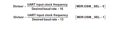
The baud_divisor value is used to define a baud rate of 115200 based on the hardware clock frequency. This value is written into two registers that represent the high and low bits of the baud rate to set, UART_DLL and UART_DLM for low and high bits respectively. The documentation regarding the baud divisor calculation comes from the processor technical reference manual (TRM). At the time of writing, the calculation is provided in section 4.4.4.2.1. Taking the clock-frequency from the device tree, in this case 48,000,000 decimal, and dividing it by desired baud rate x 16 results in a baud divisor of 26. The 16 comes from the 16x oversampling mode. The formula 48000000 / 16 / 26 gives an effective baud rate 115384, close enough to the desired baud rate of 115200.
You'll notice in the TRM that the 16x oversampling mode requires setting the mode definition register MDR to 0x0. This register, along with the other serial registers, is defined in the include serial_reg.h file and named UART_OMAP_MDR1. The register is described in the UART Registers section of the TRM. Per the TRM, the register's default mode is disabled, defined as a macro with value 0x7 named UART_OMAP_MDR1_DISABLE. Even though this is the default mode, it is a good idea to explicitly set it before configuring the UART. This is accomplished by writing that flag to the MDR1 register (the reg_write routine is covered later):
reg_write(dev, UART_OMAP_MDR1_DISABLE, UART_OMAP_MDR1);
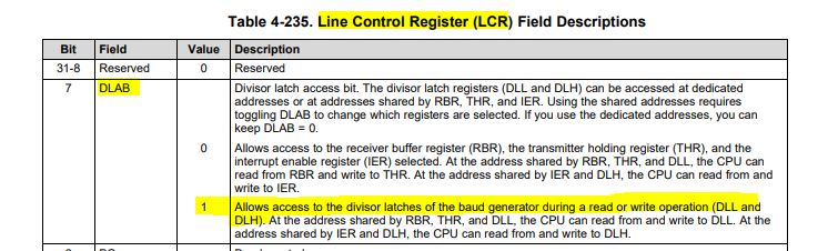
Next, the line control register UART_LCR is cleared by writing 0x0. To enable write access ot the baud divisor registers UART_DLL and UART_DLM, the device latch access bit (DLAB) must be set. This information is found in the UART_LCR register definition in the TRM. There is a macro for this flag, UART_LCR_DLAB, defined as 0x80. That flag is written to the UART_LCR register, followed by the high and low bits of the baud divisor into UART_DLM and UART_DLL respectively:
reg_write(dev, UART_LCR_DLAB, UART_LCR);
reg_write(dev, baud_divisor & 0xff, UART_DLL);
reg_write(dev, (baud_divisor >> 8) & 0xff, UART_DLM);
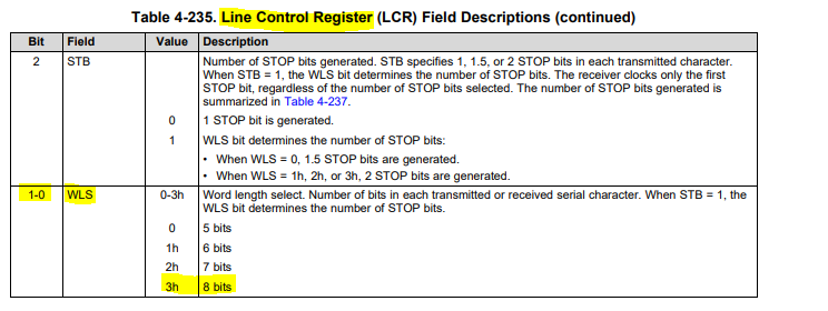
Next, the word length is set to 8 bits using another flag, UART_LCR_WLEN8, written to the line control register. This flag has a value of 0x3 which matches what is expected in the TRM LCR register definition.
reg_write(dev, UART_LCR_WLEN8, UART_LCR);
Lastly, flags are written to the uart FIFO control register, UART_FCR.
reg_write(dev, UART_FCR_CLEAR_RCVR | UART_FCR_CLEAR_XMIT | UART_FCR_ENABLE_FIFO, UART_FCR);
reg_write(dev, UART_OMAP_MDR1_16X_MODE, UART_OMAP_MDR1);
The UART_FCR_CLEAR_RCVR flag clears the receive First In First Out (FIFO), UART_FCR_CLEAR_XMIT clears the transmit FIFO, and UART_FCR_ENABLE_FIFO enables the FIFO. The FIFO buffer will store bytes as they are received until a receive interrupt is triggered, at which point the interrupt handler in the driver will read the bytes into the circular buffer. The interrupt is triggered at a configurable "high water mark" indicating the buffer is nearly full. For this driver, this is not configured and left with the default behavior. These flags correspond to bits as defined in the TRM for the FIFO Control Register (FCR).
The second line in the snippet above enables the device by changing the line control mode to 16x oversampling as described previously.
Next, the miscdevice member of the driver data structure, mentioned briefly above, is initialized. The miscdevice device and framework will be covered in a dedicated section below.
dev->mDev.minor = MISC_DYNAMIC_MINOR;
dev->mDev.name = devm_kasprintf(&pdev->dev, GFP_KERNEL, "hw_serial-%x", res->start);
dev->mDev.fops = &hw_fops;
dev->mDev.minor - This line provides a minor version number for the miscdevice. The macro MISC_DYNAMIC_MINOR provides a dynamically allocated minor number. The major version number for all miscdevice devices is already reserved in the kernel, assigned a value of 10. The linux kernel identifies devices by a major and minor number pair. Many major numbers are reserved in the kernel, so the kernel provides a mechanism for devices to request dynamically allocated major numbers.dev->mDev.name - This line creates the device name string. This is the name of the device file that will appear in /dev. Because this driver serves multiple devices, this string is created using a field that is unique to each device; in this case, the resource start address.dev->mDev.fops - This registers the file operations structure described above with the miscdevice framework.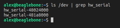
Once the miscdevice is initialized, it is registered with the kernel:
int error = misc_register(&dev->mDev);
if (error)
{
    pr_err("%s: misc register failed.", __func__);
    return error;
}
misc_register takes a pointer to the miscdevice that was just initialiazed. If the returned value is non-zero, an error message is printed and the error code returned.
The next action in probe is to assign the driver's data structure to a private data field on the platform_device field's device structure. This will make the driver's data structure accessible within the various callbacks the kernel will use. For this driver, those callbacks are the remove routine and the interrupt handler.
dev_set_drvdata(&pdev->dev, dev);
dev_set_drvdata takes a pointer the platform device as the first argument and the private data pointer to associate with it as the second. Note that dev, the driver's data structure that was just initialized, was allocated in kernel memory at the beginning of the probe routine. The use of this private data field will be described below.
The final step in the probe routine is to enable the UART receive interrupt. Once this is enabled, the interrupt handler will be called whenever data is received on the UART device.
//Enable RX interrupt
reg_write(dev, UART_IER_RDI, UART_IER);

return 0;
Enabling the interrupt is accomplished by writing the UART_IER_RDI flag to the UART_IER register. UART_IER is the interrupt enable register, defined in the TRM. The flag UART_IER_RDI is the UART "receive data" interrupt, defined as 0x1 in serial_reg.h. This can be seen in the TRM:
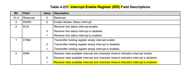
The probe routine returns a value of 0 to indicate that all of the above operations were succesful and did not result in an early error-code return.
Recall that above, when the probe routine was registered with the platform_device structure, a remove routine was also provided. This routine is the cleanup routine responsible for undoing what probe does when the device is unloaded or the driver removed. The signature of the function is the same as probe:
static int hw_remove(struct platform_device *pdev)
The argument pdev is the pointer to the same platform device intialized in probe.
First, the remove routine disables the runtime power management that was previously enabled:
pm_runtime_disable(&pdev->dev);
pm_runtime_disable is the counterpart to pm_runtime_enable. It will verify if there are any pending runtime power managment requests on the device, wait for them to complete, then disable power management of the device.
Next, the driver must unregister the miscdevice registered in probe. This provides an example of why the driver data structure was assigned to the private data field of the device member of the platform device:
   struct hw_serial_dev *dev = dev_get_drvdata(&pdev->dev);
   misc_deregister(&dev->mDev);
   return 0;
The dev_get_drvdata obtains the private data pointer that was set in probe that points to the driver data structure. This gives the remove routine access to all of the parameters that were initialized before. That allows remove to access the miscdevice and pass it to the misc_deregister routine, deregistering the device from the misc_framework. Because the driver data structure was allocated in managed memory, it does not need to be explicitly freed.
A return value of 0 indicates that the operation was successful.
The probe routine, and others, make use of helper functions for writing to and reading from the various UART registers. The register locations are offset from the resource base address stored in the driver data structure regs field. The serial_reg.h file contains the standardized set of UART registers. These registers are reused by many devices from many manufacturers. If one compares the registers in serial_reg to the actual offsets in the TRM, it is apparent that they do not match.
#define UART_IER	1	/* Out: Interrupt Enable Register */
//...
#define UART_IIR	2	/* In:  Interrupt ID Register */
//...
#define UART_LCR	3	/* Out: Line Control Register */
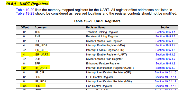
However, on close inspection, one will notice that the actual register offsets are the defined value multiplied by four. eg. UART_LCR * 4 = 12 = 0xC which matches the TRM. The reg_write and reg_read will take care of the conversion when writing to the registers.
First, the reg_read routine:
static unsigned int reg_read(struct hw_serial_dev *dev, int offset)
{
    spin_lock_irqsave(&dev->lock, dev->irqFlags);
    unsigned int ret = ioread32(dev->regs + (4 * offset));
    spin_unlock_irqrestore(&dev->lock, dev->irqFlags);
    return ret;
}
The reg_read routine takes a pointer to the driver data structure and an offset. In the places this routine is called, the offset is always a register defined in serial_reg.h. The spin_lock_irqsave routine locks the spinlock member of the data structure. This prevents concurrent access to the registers. This version of the spin_lock routine saves the interrupt enabled/disabled state into the irqFlags member so it can be restored in the corresponding spin_unlock_irqrestore call. The next line uses a routine provided by the kernel, ioread32 in the included io.h file. This reads 32 bits from the specified address. The argument given to ioread32 is the address to read. It is constructed from the dev->reqs field that was initialized in probe to point to the base address of the io resource associated with the UART device. As mentioned, the offset is multiplied by four to obtain the actual offset. The spin_lock is unlocked and the value is returned.
Next, the reg_write routine:
static void reg_write(struct hw_serial_dev *dev, int val, int offset)
{
    spin_lock_irqsave(&dev->lock, dev->irqFlags);
    iowrite32(val, dev->regs + (4 * offset));
    spin_unlock_irqrestore(&dev->lock, dev->irqFlags);
    return;
}
This routine is similar to reg_read, except for the additional argument, int val, which is the value to write to the given address. The mutual exclusion via spin_lock and calculation of the register address is the same. The ioread32 counterpart, iowrite32, writes the given value to the address.
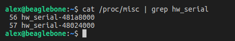
The miscdevice framework I've mentioned above can be described as "thin" wrapper for a "character" device driver. It provides a framework for drivers that don't fall in to other predefined frameworks (e.g serial, though it is important to remember that "real" UART driver would utilize such a framework). A character driver is a simple device driver that provides a set of file operations for user-space applications to interact with. As described above, this driver implements open, close, read, and write, provided in the file operations structure. The misc_framework takes care of the driver registration process like major/minor number allocation and creating an entry in the device directory, /dev. Once registered, the misc driver can be seen with its dynamically allocated minor number in /proc/misc:
The device in /dev/ shown in the screenshot in the probe routine section, can (once the permissions are set) be opened, read and written like a normal file. Those operations will call the functions pointed to in the file operations structure. The function signatures required for these routines can be seen in the definition of struct file_operations in fs.h.
The open routine, hw_open for this driver, does not perform any work; rather, it simply returns a 0 to indicate a successful operation. Likewise for the close routine, hw_close.
/*********************************************************/
static int hw_open(struct inode *inode, struct file *file)
{
return 0;
}

/*********************************************************/
static int hw_close(struct inode *inodep, struct file *filp)
{
return 0;
}
struct inode *inode - This argument is a Linux data structure that contains information about a file in memory, in this case, the driver's /dev entry.struct file *filep - This argument is a Linux data structure that exists for every open file.The read and write routines provide the interface for user-space applications to interact with the driver.
static ssize_t hw_read(struct file *file, char __user *buf, size_t size, loff_t *ppos)
{
    struct miscdevice *mdev = (struct miscdevice *)file->private_data;
    struct hw_serial_dev *dev = container_of(mdev, struct hw_serial_dev, mDev);
    wait_event_interruptible(dev->waitQ, dev->buf.length > 0);

    char ret = read_circ_buff(dev);
    copy_to_user(buf, &ret, 1);
    return 1;
}
struct file *file - This is the file handle for the /dev/ entry of the miscdevice created for this driver.char __user *buf - This is the pointer to the user-space memory buffer to populate.size_t size - This is the size in bytes the user is requesting.loff_t *ppos - This is an offset, specified by the user, that indicates where the read should start. Since this driver only reads whatever is in the circular buffer, this argument is ignored.The first line gets a pointer to the driver data structure's miscdevice member (dev->mDev). The pointer to the miscdevice is stored in the file handle's private_data member. In order to get access to the driver data structure, the container_of macro is used. The macro calculates the address of the parent object that contains the miscdevice. The details of this macro can be viewed in kernel.h.
Next, a call is made to wait_event_interruptible. The arguments to this call are the wait_queue member of the driver data structure and a condition to check; in this case, the ring buffer is checked for available bytes to read (buf.length > 0). A calling process that encounters this line will be put to sleep until the condition is met. This allows calling processes to wait for data to come across the UART. Multiple processes will be put to sleep and awoken in FIFO order. The corresponding wake-up process is in the receive interrupt handler, covered later.
Next, the character to return is pulled from the circular buffer using the read_circ_buff helper function described above. This character is copied from kernel memory to user-space memory with a call to copy_to_user. This routine, and it's counterpart copy_from_user are provided in the included uaccess.h file.
The return value of the read routine is usually the number of bytes read. Since this driver only reads one byte at a time, the return value is hardcoded as 1.
The write routine is defined as:
static ssize_t hw_write(struct file *file, const char __user *buf, size_t len, loff_t *ppos)
{
    struct miscdevice *mdev = (struct miscdevice *)file->private_data;
    struct hw_serial_dev *dev = container_of(mdev, struct hw_serial_dev, mDev);

    char kmem[len + 1];
    copy_from_user(kmem, buf, len);
    int i;
    for (i = 0; i < len; i++)
    {
        if (kmem[i] == '\n')
        {
            write_char(dev, '\n');
            write_char(dev, '\r');
        }
        else
        {
            write_char(dev, kmem[i]);
        }
    }
    return len;
}
The signature of this routine is identical to hw_read.
struct file* file - Same as described above.char __user *buf - This is the pointer to the user-space memory buffer containing the data to writesize_t size - This is the size in bytes the user is requesting be writtenloff_t *ppos - Same as described above.A pointer to the driver data structure is obtained in the same manner as reg_read. A kernel-space memory buffer kmem is declared, large enough to hold the data being written. A call to copy_from_user copies the user-space data to the kernel space buffer. Next, the kmem buffer is iterated, passing each byte to a helper function called write_char. Notice that when the driver encounters a newline character \n, it actually writes a newline carriage return \n\r over the UART. The return value of write is the number of bytes written. Since the driver always attempts to write len bytes, it simply returns len.
An important note here is that this minimalist driver does not do a lot of the safety and sanity checks that a "real" driver would do. Arguments like the buffer size used to allocate the kernel-space stack buffer could easily lead to crashes/unexpected behavior.
So far, the misc_framework has only provided the user <-> driver interface. The driver <-> device interface is comprised of two routines. First a routine to write characters to the UART:
static void write_char(struct hw_serial_dev *dev, char c)
{
    unsigned int lsr = reg_read(dev, UART_LSR);
    while (1)
    {
        if (lsr & UART_LSR_THRE)
        {
            break;
        }
        lsr = reg_read(dev, UART_LSR);
    }
    reg_write(dev, c, UART_TX);
}
This routine, called form the hw_write routine in the miscdevice section described above, takes a pointer to the driver data structure dev and a character to write to the UART, c. First, the line status register, UART_LSR is read. The line status register contains a field for "Transmit-hold-register empty", seen in serial_reg.h:
#define UART_LSR_THRE 0x20 /* Transmit-hold-register empty */
If this bit is set, it indicates that the transmit FIFO is empty. write_char loops infinitely, checking that condition until it is met. Next there is a call to reg_write that sends the character over the UART by writing it to the transmit register, UART_TX. This driver does not cover the time-of-check to time-of-use (TOCTOU) case where the UART_LSR_THRE bit could change between the last reg_read call and the reg_write call. This would be another example of a consideration to make in a "real" driver.
Recall that in the probe routine an interrupt handler was registered to the UART receive interrupt. This handler is responsible for recieving data from the UART and copying it to the ring buffer so it may be read by a user-space application as described in the miscdevice section.
static irqreturn_t irqHandler(int irq, void *d)
{
    struct hw_serial_dev *dev = d;
    do
    {
        char recv = reg_read(dev, UART_RX);
        write_circ_buff(recv, dev);
        wake_up(&dev->waitQ);
    }
    while (reg_read(dev, UART_LSR) & UART_LSR_DR);
    return IRQ_HANDLED;
}
The interrupt handler function signature is defined in the included interrupt.h file. The first argument is the IRQ number. The second argument is a pointer to the private data registered when the IRQ was requested with devm_request_irq in the probe routine. In this case, it's the driver data structure.
The interrupt handler reads the UART receive register, UART_RX to get the the first byte in the receive FIFO using the reg_read helper function. Next the byte is added to the ring buffer with the write_circ_buff utility function. A call to wake_up, passing the wait_queue member of the driver data structure, wakes up any processes that were queued waiting for data in the hw_read routine as described above. This process is repeated until there is no more data in the receive FIFO. This condition is checked by reading the line status register, UART_LSR and checking if the UART_LSR_DR flag is set. This flag, also from serial_reg.h, is set whenever receive data is ready, and cleared otherwise. The return value, IRQ_HANDLED notifies the kernel that the interrupt was serviced by this device driver. It is important to note that the interrupt will continue to fire, regardless of the return value, until the UART_RX register is read and the FIFO is below the "high water mark" as described previously. It is the combination of the UART_RX read and the IRQ_HANDLED return value that satisfies the interrupt.
Taken together, all of these data structures and functions comprise a functioning, albeit simplistic, serial UART driver. To test the driver, the kernel and device tree binary need to be deployed and booted on the Beaglebone. (Again, for reference, my previous post covers this). Next, the kernel module should be compiled per the Building a kernel Module section of this post. (There are some compiler warnings I chose to ignore for this post, but otherwise it should compile in a properly configured build environment). The resulting .ko file is the kernel module. This file should be transferred to the Beaglebone, e.g.:
scp hw_serial.ko beagle:~/
Next, on the Beaglebone, install the kernel module using the insmod command:
sudo insmod hw_serial.ko
For reference, the opposite of this command, should you want to unlaod the module, is rmmod:
sudo rmmod hw_serial.ko
When the module is loaded, the new entries for each UART device can be found in /dev/uart
Recall that the device name provided by the driver used the resource start address as the suffix to uniquely identify UART2 and UART4. The addresses for both resources are from the device tree include, am33xx.dtsi that the custom device tree extended:
uart2: serial@48024000 ...
uart4: serial@481a8000 ...
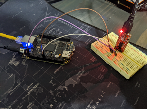
This means that the device entry hw_serial-48024000 corresponds to UART2. Toward the beginning of this post, the pin-out for UART2 on the P9 extension header was obtained from the Beaglebone Black System Reference Manual. The pins for UART2 were RX: 22 TX: 21. A serial device can be attached to these two pins to test the device driver. I used an FTDI USB Serial Adapter like I used in my previous post. It's a simple 3-wire hookup:
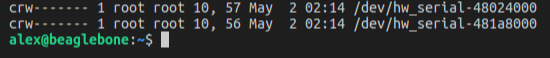
An easy way to communicate with the device is to use the cat utility. Internally, cat will call the open and read functions the driver provides. Before the device can be read or written to, the file permissions must be set. By default, the file is only accessible to root:
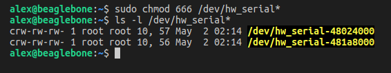
To make the file globally readable and writeable, use the chmod command:
sudo chmod 666 /dev/hw_serial*
These steps, i.e. deploying the module to the Beaglebone, running insmod, and fixing the permissions, can be scripted. This can be useful if you are modifying/executing frequently during the development process.
Now, the device can be opened with cat. Using my PC and the USB serial adapter, I sent the string "hello" from the left side, and the characters are printed on the Beaglebone on the right:
To send the string "Hi!" back, I used the echo command on the Beaglebone and redirected the output to the device file:
This post was long, but hopefully it provided some useful information. The information gathering and incremental development process demonstrated here provides useful skills that are applicable to a variety of projects. I learned a great deal throughout the development of this driver, and I have more improvements to make in future posts. Many tutorials/guides on the topic tend to gloss over the minutia involved in this process; I hoped to avoid providing a "magic recipe" and instead develop a foudnational/intuitive understanding of what this driver does and how to "get there".
pr_info to print to the system log (/var/log/syslog) is a remarkably useful way of verifying or understanding what is happening at runtime.