This post is a continuation of my previous posts covering my configurable digital logic implementation of the AES-256 cryptographic algorithm. In this post I'll cover the refactoring I did to improve my implementation and make the design synthesizeable. Previously, the architecture for the module was poor and could not be synthesized to run on real hardware. This was an expected outcome as I learn to write verilog. I've detailed some of the changes I made below.
I have read and heard mixed responses in regard to using for loops in synthesizeable code. It is my understanding that loops are unwound during synthesis, and large loops can result in large resource consumption. I decided to remove most of the loops in my AES implementation. One example is the key scheduling portion of the algorithm. previously, I relied on a loop to iterate over the key words:
    if(consent_reg == KEY_WORDS)
    begin
        rconIdx = 0;
        for(x = 8; x < 60; x++)
        begin
            if(x % 8 == 0)
I replaced the loop with a state machine that performs the same iteration over the key words. The main state machine (covered below) enables the key scheduling state machine and waits for it to finish.
///This state machine calculates the
///the round key words and round keys, setting its
///"done" register when finished
reg [5:0] table_idx;       //Key word index
reg [3:0] rcon_idx;        //Round constant index
reg [3:0] rk_idx;          //Round key index
parameter [4:0] KW_IDLE  = 4'b000, //Idle state
                KW_CALC  = 4'b001, //Calculate state
                KW_SCHED = 4'b010, //Form round keys
                KW_DONE  = 4'b011; //Done state
reg [2:0] kw_state;  //State machine states

//Done signal
wire KEY_WORDS_DONE;
assign KEY_WORDS_DONE = (kw_state == KW_DONE);
always @(posedge clock)begin
There were other places I relied on looping, mostly for convenience:
    for(row = 0; row < 4; row++)
    begin
        for(col=0; col<4; col++)
        begin
            matrix[row][col] = sbox(matrix[row][col]);
        end
    end
These loops were easily replaced by unwinding them manually.
    else if(state_reg == SUB_BYTE) begin
        //Peform S-box Substitutions
        sub_byte_matrix[3][3] <= sbox(round_key_matrix[3][3]);
        sub_byte_matrix[2][3] <= sbox(round_key_matrix[2][3]);
        sub_byte_matrix[1][3] <= sbox(round_key_matrix[1][3]);
        ...
        sub_byte_matrix[1][0] <= sbox(round_key_matrix[1][0]);
        sub_byte_matrix[0][0] <= sbox(round_key_matrix[0][0]);
    end
One of the "rookie" mistakes I made was trying to read and write from the same register in multiple blocks. I replaced the single state matrix with multiple state matricies for the output from each step in the encryption process. Any one state matrix is only written by one always block and read from the successive block.
//This list of state matricies forms the data pipeline
reg [7:0] initial_matrix[0:3][0:3];   //Initial state matrix
reg [7:0] round_key_matrix[0:3][0:3]; //Round key matrix
reg [7:0] sub_byte_matrix[0:3][0:3];  //Byte substitution matrix
reg [7:0] shift_row_matrix[0:3][0:3]; //Shift rows matrix
reg [7:0] mix_col_matrix[0:3][0:3];   //Mix columns matrix
In the same vein, I combined the key scheduling stages into one state machine (described above).
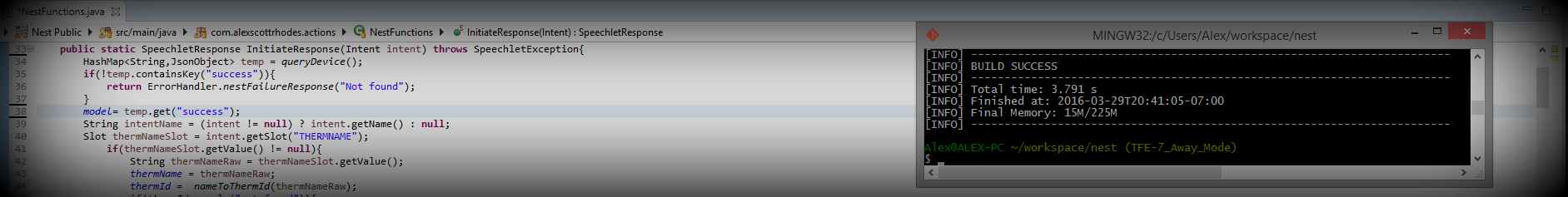
I refactored my main state machine to use initialization/completion logic that's more inline with examples I've seen in Xilinx sources and other source files. Additonally, I tried to update my indentation and formatting to match conventions I've seen.
To verify that my AES module can be synthesized and run on hardware, I created a basic block design for the Zynq7000 that contains a Xilinx VIO core, Zynq7000 processing system, and my AES module.
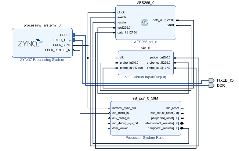
The VIO allows for manual input and output to the AES core. I ran an empty software application and used the Vivado hardware manager view to run the AES module with the same input data and key that I used in the test bench. The module functioned as designed and the output matches the expected output.
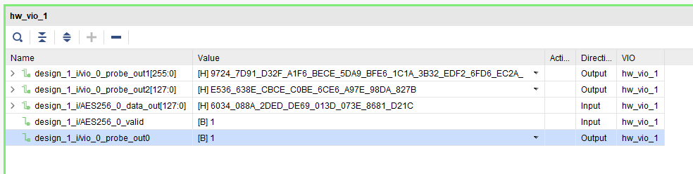
Input key:
97247d91d32fa1f6bece5da9bfe61c1a3b32edf26fd6ec2a6187ba777fc3c1d8

Input data:
e536638ecbcec0be6ce6a97e98da827b

Starting encryption.
Data out: 6034088a2dedde69013d073e8681d21c
Valid: 1
Mistakes/bad design aside, I think my AES module is coming along nicely. Now that I have the module running on the hardware, I intend to use it in a practical design, using AXI to encrypt data stored in the PS DDR.